Well Manager® System Features & Specifications
Explore the components, controls, tank configurations, pump options, and technical specifications that make up the Well Manager® system.
At-a-Glance System Specifications
- Water Source: Private well
- Recommended Well Yield: Approximately 0.25 GPM+
- Collection Method: Timed water collection
- Well Pump Control: Controlled by Well Manager®
- Water Storage: 100+ or 210+ gallon tank options
- Tank Configurations: Vertical, Horizontal & Low Horizontal
- Pressure Delivery: Booster / VFD pump
- Standard Inlet: 1"
- Control Panel: UL Listed
- Tank Level Control: High, Low & Overfill protection
- Flow Monitoring: Included
- System Voltage: 115V dedicated 15A circuit
- Pump Voltage: Electrical requirements vary by selected pump
- Standard Installation Location: After sediment filtration; before water treatment
Need Help Choosing a Well Manager®?
What Makes Up a Well Manager® System?
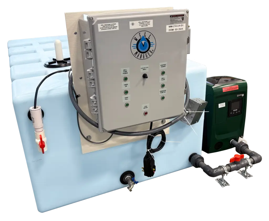
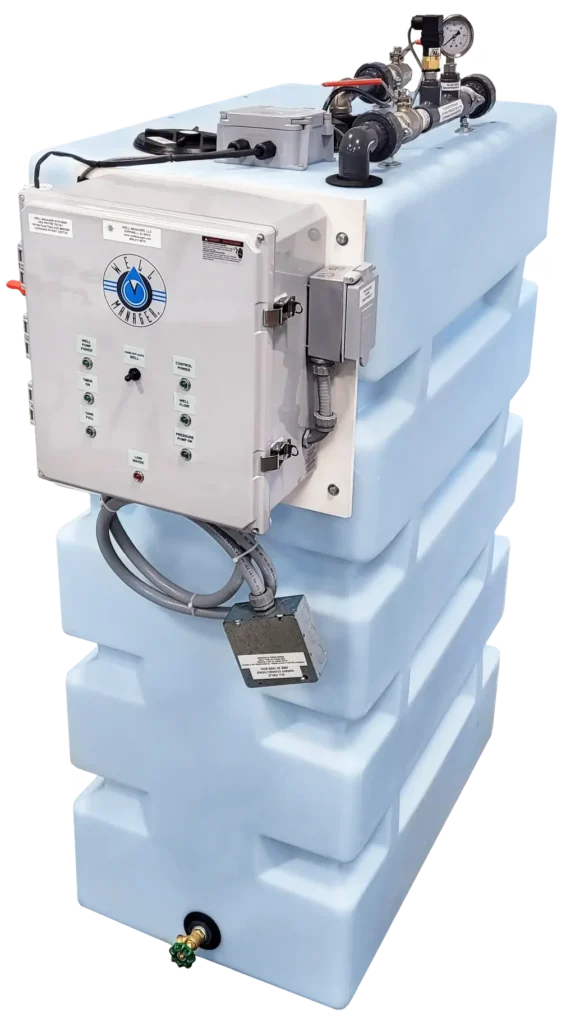
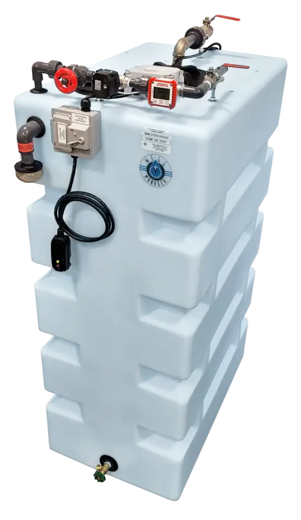
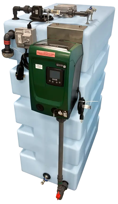
The Well Manager® combines water storage, well pump control, tank-level monitoring, flow detection, and pressure delivery into one coordinated system. Each component has a specific role in controlling how water is collected, stored, and supplied to the building.
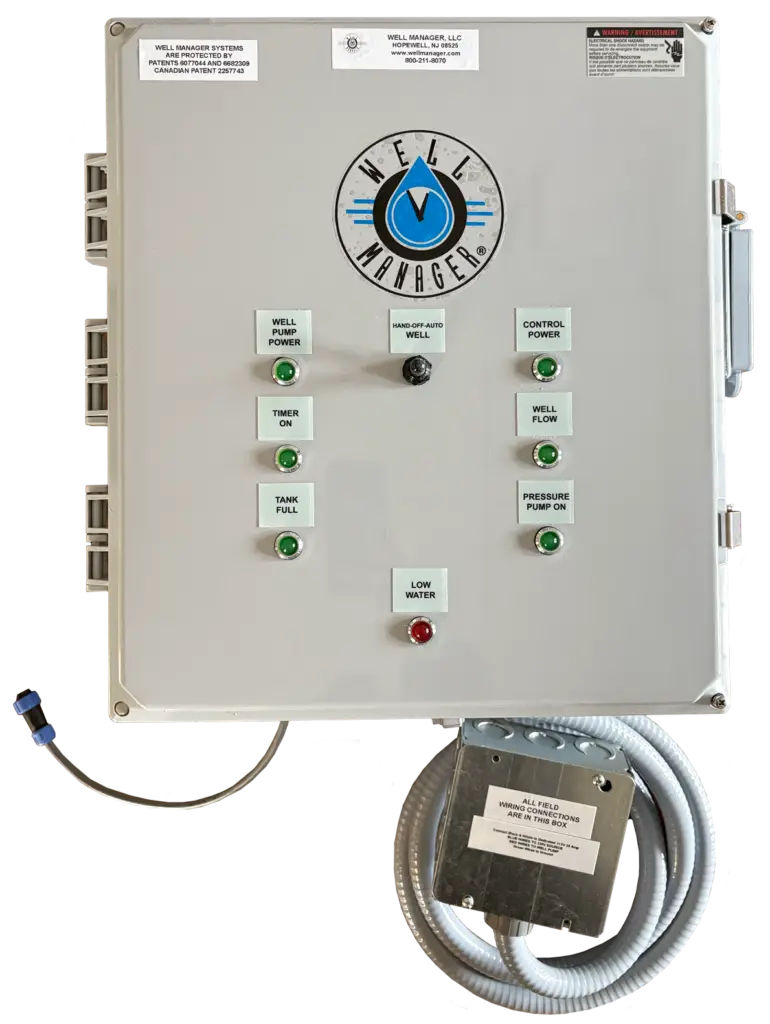
UL-Listed Control Panel
Controls the well pump, collection timing, tank level signals, flow detection, and system operation.
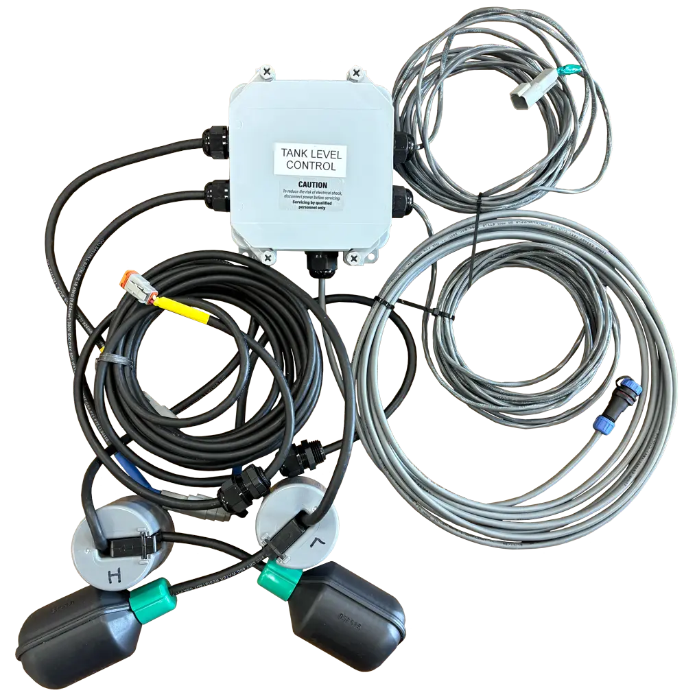
Tank Level Control
Uses high- and low-level floats to communicate tank water levels to the control panel and manage collection.

Flow Detector
Confirms incoming water flow while the well pump is operating and helps protect against loss of water supply.
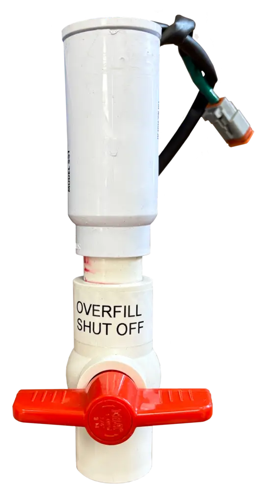
Overfill Protection
A separate safety float provides redundant shutoff protection if the normal high-level control does not stop collection.
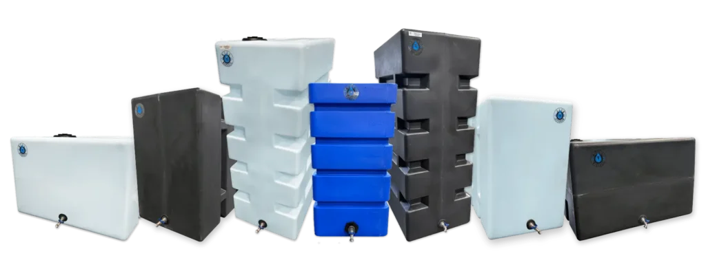
Water Storage Tank
Stores collected well water so household demand is separated from the well’s immediate production rate.
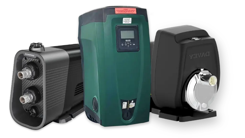
Pressure Pump
Draws from stored water and delivers consistent pressure and flow to the home or building.
Well Pump Junction / Control Connection
Allows the Well Manager® to take control of well pump operation rather than relying on the existing pressure switch.
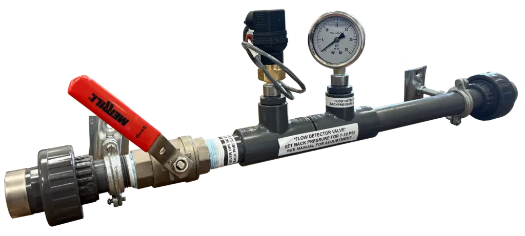
Manual Throttling / Backpressure Control
Allows incoming flow to be adjusted while maintaining the required backpressure for proper well pump operation.
Well Manager® Control Panel
Complete Control of Water Collection
Well Manager® UL-listed control panels are purpose-built to manage one-well, two-well, or three-well systems. Each panel is newly built and engineered for the exact number of wells it controls, providing safe, reliable pump management, flow monitoring, and system protection—all from a centralized control point.
Digital Well Pump Timer
Adjustable run and recovery periods allow collection to be matched to the well’s production.
Indicator Lights
Provide visible system status for power, pump operation, water flow, tank level, and alarms.
Individual Circuit Controls
Separate controls for the panel, well pump, and pressure pump simplify servicing and troubleshooting.
Replaceable Components
The proprietary panel is manufactured for Well Manager® using serviceable industrial control components.
Well Manager® Single-Well Control Panel
The Well Manager® Single-Well Control Panel is the command center for one-well systems, designed to replace the traditional pressure switch and provide precise, reliable control of well operation. Using digital timing and flow feedback, it manages water collection, protects the pump, and ensures consistent water availability.
Clearly labeled status indicator lights—including Tank Full, Well Flow, Pressure Pump On, and Low Water—provide at-a-glance visibility into system operation, making monitoring simple for homeowners and technicians alike.
Key Features
- Hand-Off-Auto switch for automatic operation, manual control, or servicing
- Status indicator lights for real-time system monitoring and alerts
- Programmable control of well pump run times, rest periods, pressure, and water flow
- UL-listed panel construction designed for long-term durability and reliability

Well Manager® Two-Well Control Panel
Designed for homes or properties with two wells, the Well Manager® Two-Well Control Panel is engineered to manage and alternate between two wells, running one well at a time for controlled water collection and improved recovery. Each well operates on its own independent timer cycle, with adjustable run and rest periods built directly into the panel.
Duplicate indicators and controls allow each well to be monitored individually while the system balances usage to maximize water availability and protect both wells.
Key Features
- Alternates between two wells, running one well at a time
- Independent on-time and rest-time timers for each well
- Dual sets of status indicator lights for clear, at-a-glance monitoring
- Hand-Off-Auto switch for automatic operation, manual control, or servicing
- Integrated control of well pumps, pressure pump operation, and safety functions

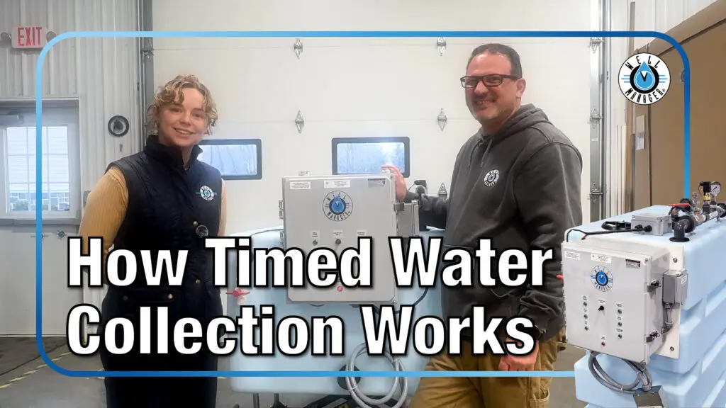
Timed Water Collection
Designed Around Your Well's Recovery
Instead of allowing the well pump to run solely in response to household demand, Well Manager® collects water according to programmed run and rest periods. This gives a low-producing well time to recover between collection cycles while gradually building a stored water supply.
Well Pump Runs
Water Is Collected
Flow Is Verified
Well Pump Stops
Well Recovers
Collection Repeats
Tank Level Control & Protection
Automatic Tank Level Management
The Well Manager® uses multiple level controls to automatically manage stored water and help protect against overfilling. Together, these components communicate water levels to the control panel and keep collection operating automatically.
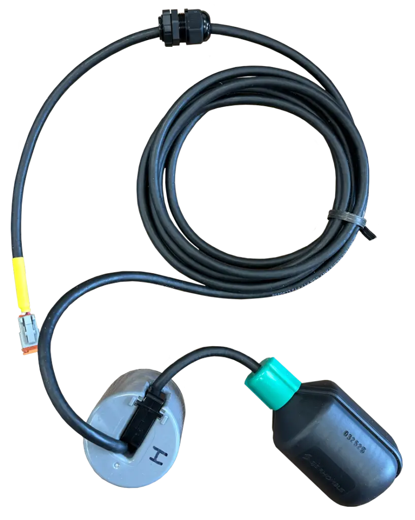
Low-Level Float
Signals when stored water has dropped and collection is needed.
High-Level Float
Stops normal collection once the tank reaches its full operating level.
Micro / Overfill Float
Provides an independent secondary shutoff for additional overfill protection.
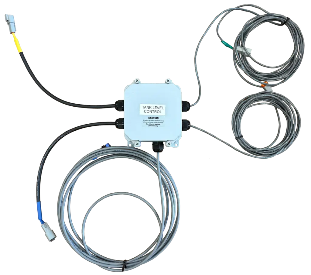
Tank Level Control Box
The Tank Level Control box monitors the water level in the storage tank and communicates with both the Well Manager® control panel and inlet assembly.
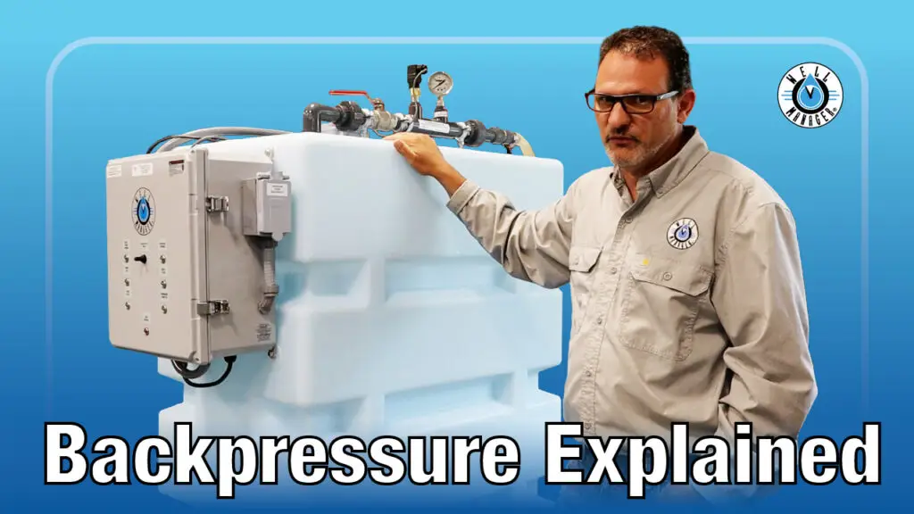
Backpressure Control
The Well Manager® maintains controlled backpressure on the well pump while water is being collected. This helps keep the well pump operating under proper conditions while the system regulates the rate at which water enters the storage tank.
Recommended Backpressure: 7–10 PSI
Planning an installation?
See plumbing requirements, electrical information, diagrams, installation videos, and common installation questions.
Water Storage Options
Water Storage Designed Around Your Space
Well Manager® systems are available with multiple tank sizes and orientations to accommodate basements, utility rooms, garages, crawl spaces, and other installation areas.
Vertical 210 gallon

L45″ x W24″ x H68″
Effective Water Storage: 195gal
Horizontal 210 gallon

L70″ x W24″ x H46″
Effective Water Storage: 185gal
Low Horizontal 210 gallon

L70″ x W37″ x H32″
Effective Water Storage: 175gal
Vertical 100 gallon

L32″ x W24″ x H56″
Effective Water Storage: 90gal
Tank Construction
- Virgin polyethylene construction
- FDA-compliant resin for potable water storage
- Ribbed construction
- 16″ vented lid
- Installed tank fitting/spigot
- 20-gallon graduations
- Multiple orientations available
Need more information about tank construction, dimensions, colors, and configurations?
Pump Options for Your Water Demand
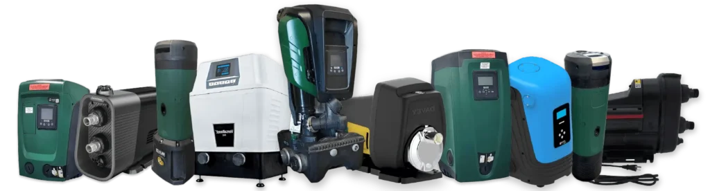
Well Manager® systems can be configured with different pressure pumps based on the required flow, pressure, electrical supply, application, and installation layout.
Bladder Tank Requirements
Installation Note: For best performance and to help prevent rapid pump cycling, install a bladder tank on the discharge side of the pump. DAB recommends sizing the bladder tank based on your pump’s normal peak flow:
- 2-gallon bladder tank – E.SYBOX Mini 3 (approximately 10 GPM)
- 4-gallon bladder tank – E.SYBOX, DTRON 2, and DIVER (approximately 20 GPM)
- 10-gallon bladder tank – E.SYBOX MAX (approximately 50 GPM)
With a Well Manager® system, the existing pressure tank can often be reinstalled after the system to serve as the bladder tank.
Where Well Manager® Fits in Your Water Line
Diagram highlights pre- and post-filtration recommendations for a complete setup.

Well
Sediment Filtration
Well Manager®
Water Treatment
Home
Bladder Tank Requirements
Installation Note: For best performance and to help prevent rapid pump cycling, install a bladder tank on the discharge side of the pump. DAB recommends sizing the bladder tank based on your pump’s normal peak flow:
- 2-gallon bladder tank – E.SYBOX Mini 3 (approximately 10 GPM)
- 4-gallon bladder tank – E.SYBOX, DTRON 2, and DIVER (approximately 20 GPM)
- 10-gallon bladder tank – E.SYBOX MAX (approximately 50 GPM)
With a Well Manager® system, the existing pressure tank can often be reinstalled after the system to serve as the bladder tank.
Planning an installation?
See plumbing requirements, electrical information, diagrams, installation videos, and common installation questions.
Learn More About Your Well Manager®
Video Testimonials

Ready to Plan Your Installation?
From plumbing and electrical requirements to system placement, startup videos, and installation FAQs, our Installation Resources walk through what you and your installer need to know.

Replacement Parts & Long-Term Serviceability
Designed to Be Serviceable
Well Manager® systems are built from individually serviceable components. Control panels, floats, flow controls, pumps, and other system components can be replaced as needed without replacing the complete system.
Looking for a replacement component?
Warranty & Support
Well Manager® systems are backed by product warranty coverage and ongoing support from our team. Individual components may have specific warranty terms based on the equipment included with your system.
Well Manager® System Warranty
Well Manager® system components are covered by a 1-year parts warranty, providing support for eligible component issues during the warranty period. More details come with Well Manager® Manual.
Pump Warranty
Pressure pumps are covered according to the applicable manufacturer’s warranty. Coverage and warranty length vary by pump model.
Questions about warranty coverage or replacement parts?
Not Sure Which Configuration You Need?
Every well and water demand is different. Our team can help determine the appropriate storage capacity, pump, and system configuration based on your well yield, household demand, available space, and pressure requirements.
Common Questions, Clear Answers
Learn More About Your Well Water
Explore expert articles on low water pressure, low-yield well solutions, well maintenance, seasonal changes, and current well water issues — all written to help you understand your system and protect your water supply.