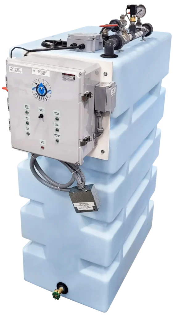
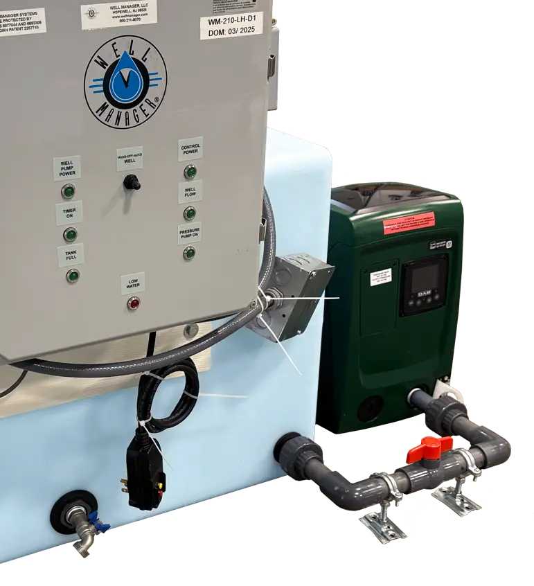
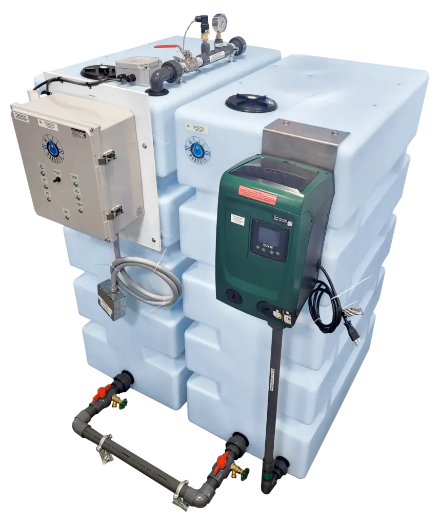
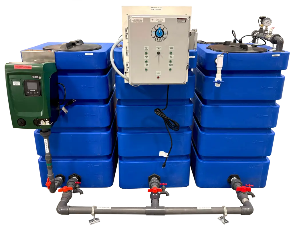
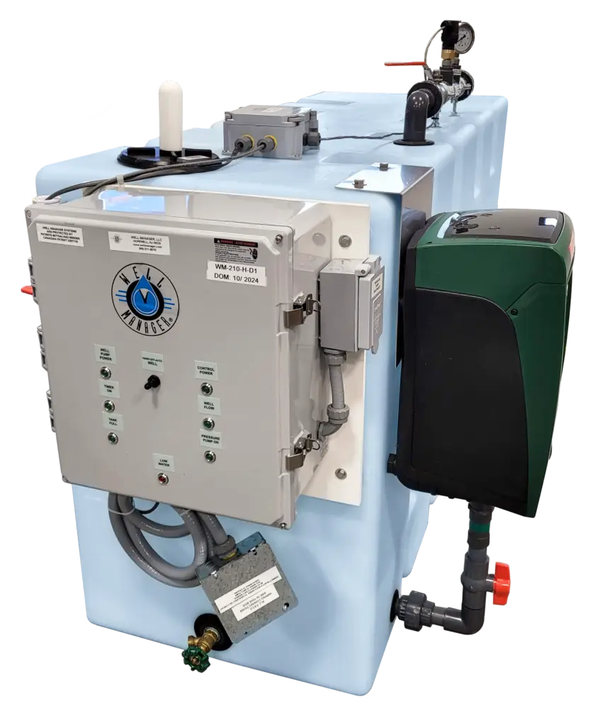
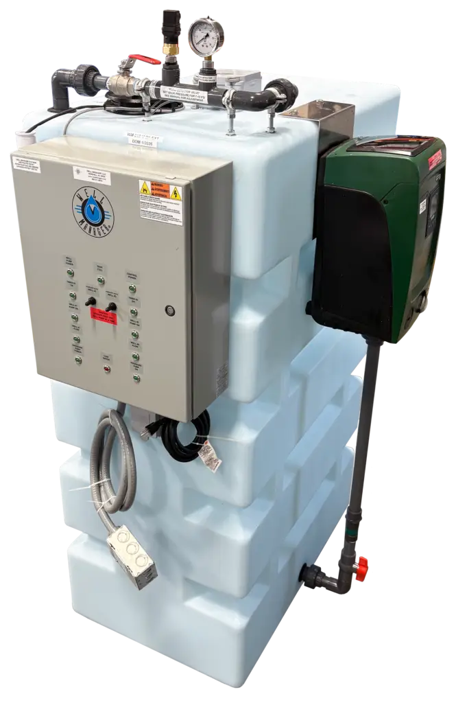
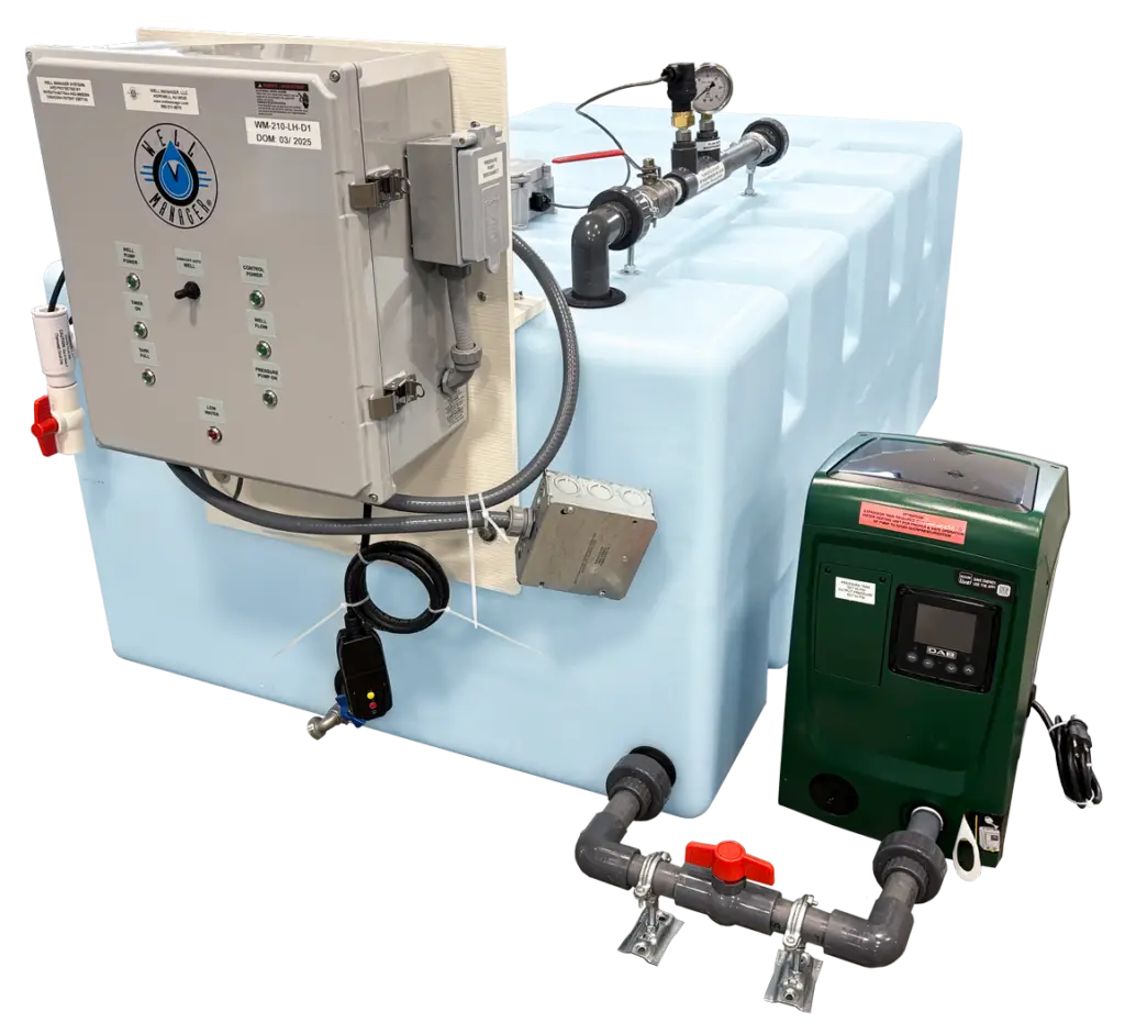
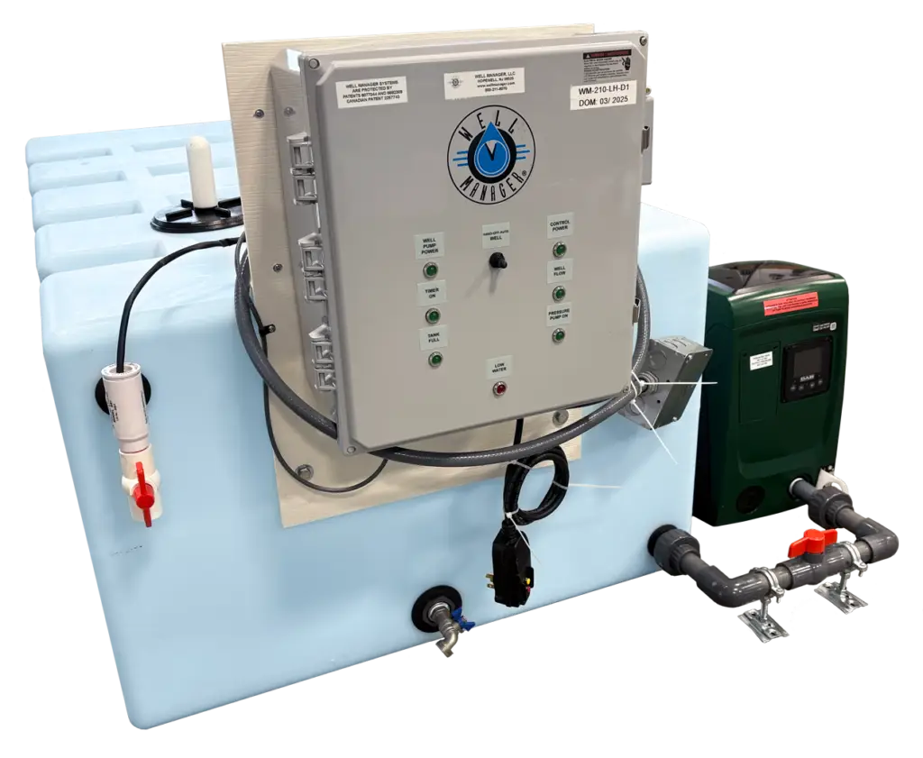
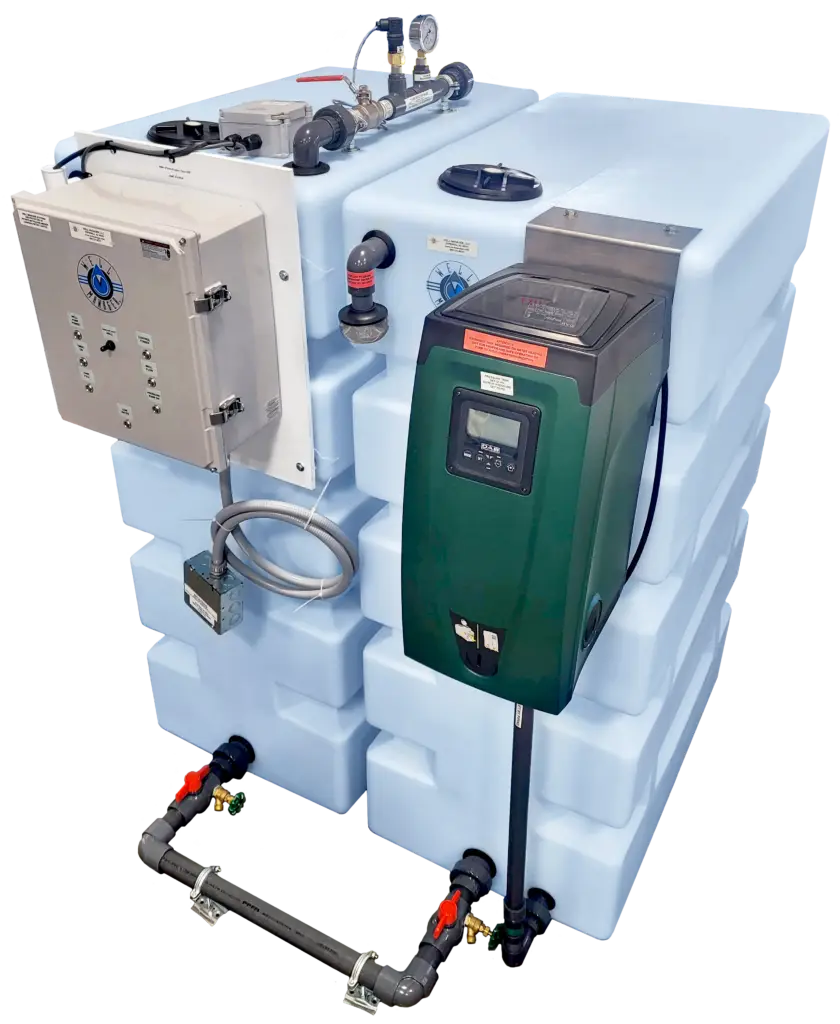
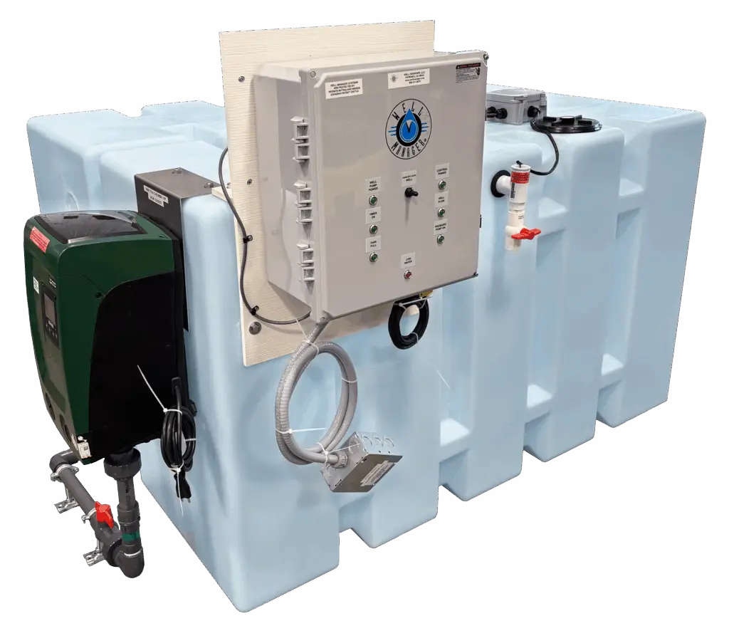
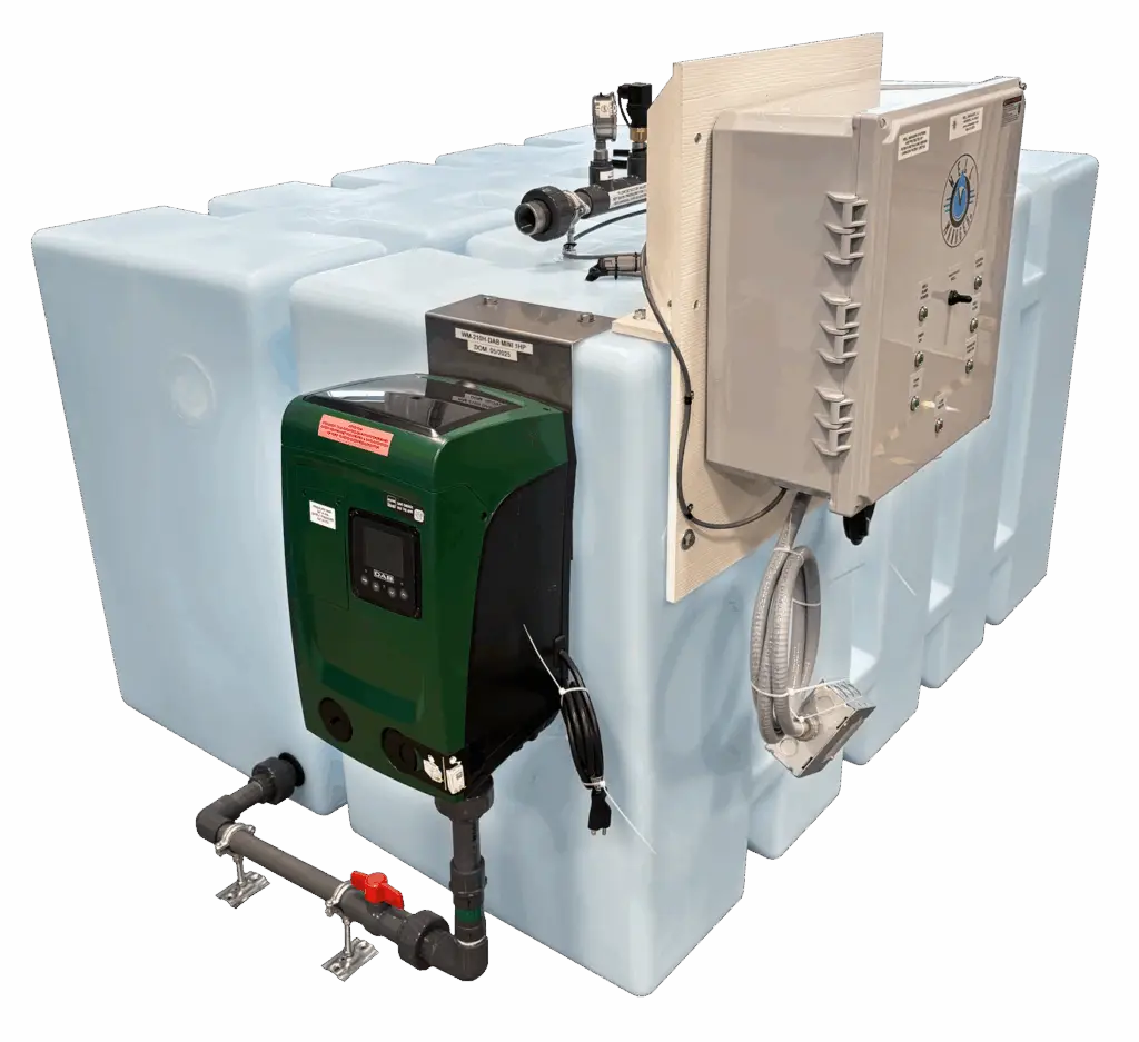
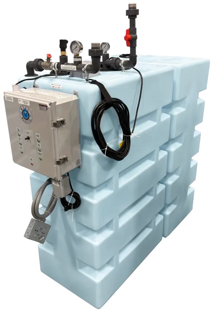
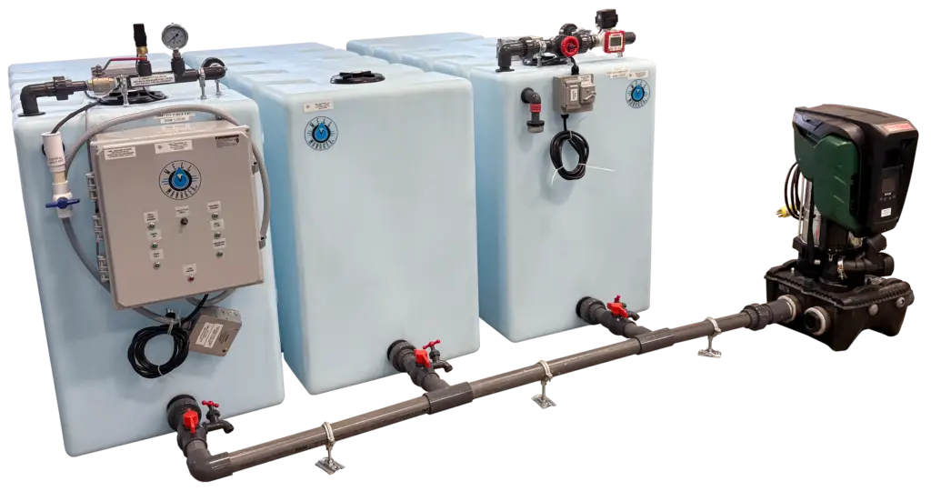
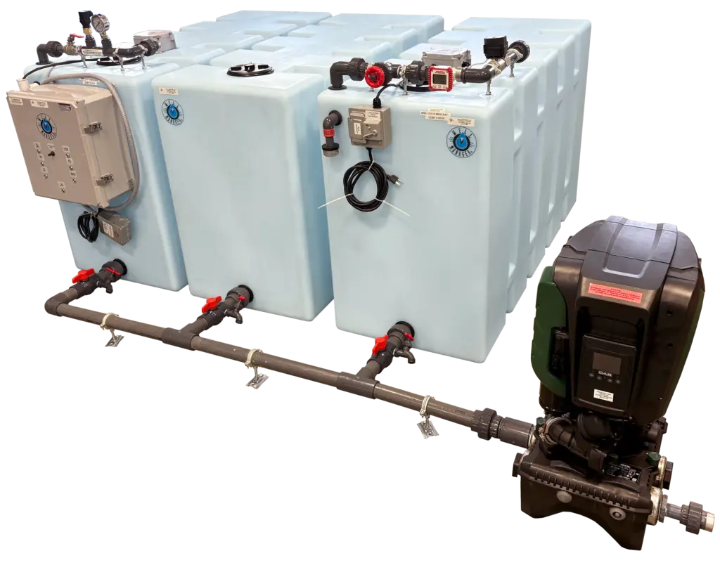
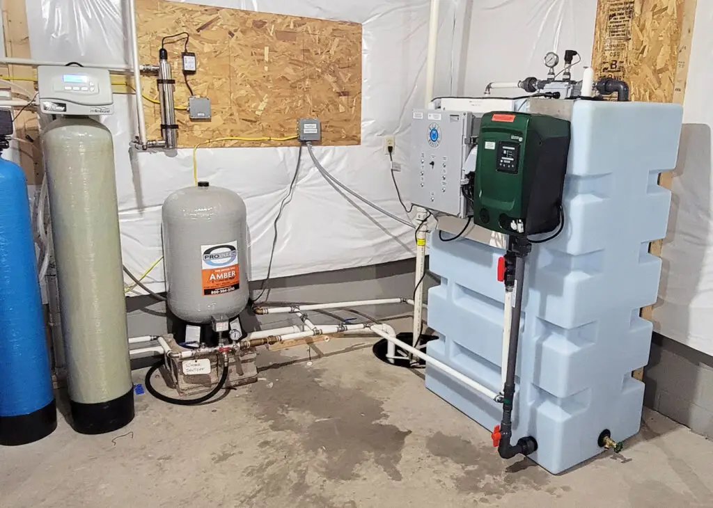
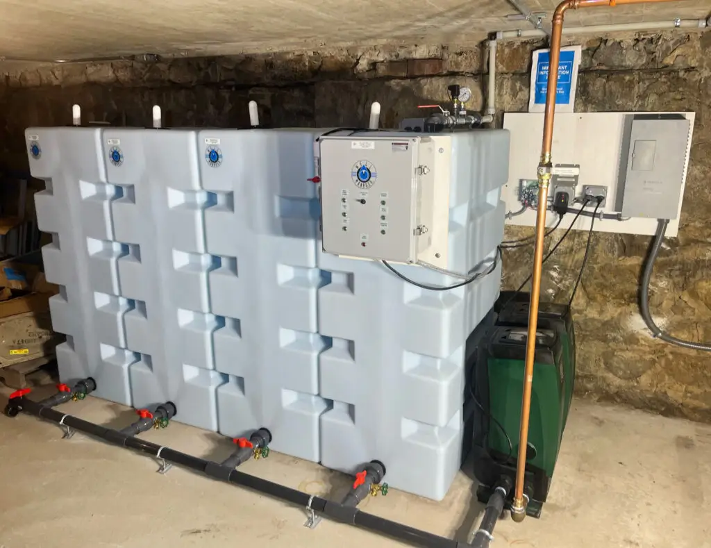
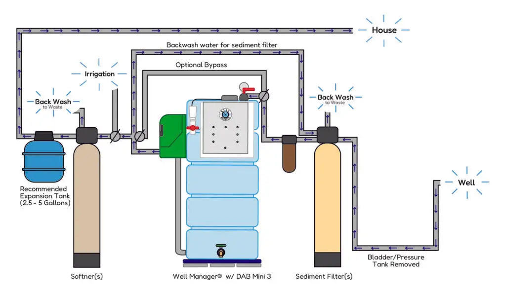
Temporary & Emergency Water Systems   PumpChamber


Well Manager® is the result of 8 years of development and field-testing. It was designed to get more usable water from low yield water wells and to deliver plumbing performance similar to that expected of a city water system. I know at first glance this sounds impossible, but if you read on you will realize that it is not.

This system will work on almost any well or combination of wells, with any type of pump or pumps and can be used to supply buildings with an expected peak demand of a few gallons per minute to those requiring 100 GPM or more.

A Well Manager® system can take a terrible well and turn it into a good source of water. For example, in a residential setting it will enable a family of four to live with a one quart per minute well with as little as 160 gallons of tank storage. The best part is that the residential system can usually be installed in a few hours, so it can literally change a family's lifestyle overnight. AND these systems are in use on wells with yields as poor as 1/10th gallon per minute.

The first morning after the system is installed our family of 4 will have enough water and pressure to take two showers at once. Everyone in the family would be able to take a 10-minute shower, use the toilet, shave, make breakfast and still have enough water to run the dishwasher - and all of this on that terrible one quart per minute well.

When we began thinking about ways to deal with low yield wells, we realized that most lack of water problems result from the way water is collected from the well, not because there is no water to collect.

The tables below demonstrate that even a one-quart per minute well can support a family of four if they have a way to collect all the water the well produces.

Per Day Requirement
Based on a range
of 75 to 125 Gallons
Per Person Per Day

Well Yield
How Much Water Do I Have?

Number of People

Per Day Requirement in Gallons Per Day

Gallons Per Minute =

Gallons Per Day

1

75 - 125 .25 360
2 150 - 250 .5 720
3 225 - 375 .75 1,080
4 300 - 500 1.0 1,440
5 375 - 625 1.5 1,160
6 450 - 750 2.0 2,880

7

525 - 875 2.5 3,600

8

600 - 1,000 3.0 4,320

9

675 - 1,125 4.0 5,760

10

750 - 1,250 5.0 7,200

A traditional storage tank (the one most well owners have) is pressurized as the pump draws water from the well. When the preset pressure is reached, the pump shuts off and waits for someone to use the water stored in the pressure tank. With a traditional system, when you don't use water the pump just sits there. The well is collecting water, but the pump isn't harvesting it and once the well fills to its static level, it too stops producing.

Looking at a low yield well in this way, the gallon per minute yield of the well is not nearly as important as the peak demand requirement, the interval at which it recurs and the amount of water the well can provide within that time interval.

For residential use, the time interval might be 24 hours if everyone showers in the morning. For a church, the interval might be seven days or, if there are scheduled events during the week, two or three days. For a vacation home in the mountains, the interval could be much longer.

The beauty of the Well Manager® is that results are predictable because the design is based on known quantities (how many gallons per minute the well provides, how many gallons per minute the well pump can deliver, and how much water you need to take care of your peak demand needs) and the pump controller is almost infinitely adjustable with regard to frequency and duration of pumping cycles.

The pumping cycles are set up to take no more water than the well can produce, so fluctuations in the well's water level are reduced. Because drawdown can be controlled, these units can also minimize "interference" between wells. Once the pumping cycles have been set up, the Well Manager® relentlessly collects water day and night, whether or not there is water being used, until the unpressurized tank(s) is full.

Pump Control Sequence of Operation

Well pump run duration and wait time between run times are selected by means of ten binary switches, which permit run or delay times from 10 seconds to 2.8 hours in 10-second increments. When power is applied to the Well Manager® control the well pump on cycle begins and the well pump starts.

If the pump starts water flowing through the pipe from the well to the atmospheric storage vessel, a flow detector enables the well pump to continue running.

If, for any reason, water does not activate the flow detector before the allotted 5 seconds elapses or water stops flowing from the source during an on cycle, power to the well pump is interrupted. This provides well pump protection in the event that well yield falls below the control setting and the well is inadvertently pumped down.

The well pump, controlled by the timer, will come on every time an "on time" or collection cycle starts unless the atmospheric storage vessel is full. Once full, a tank full float m deactivates the well pump relay.

Tank Level Control and Overfill Shut-off

If the tank full float fails to shut off incoming water, an overfill shut off device will interrupt 24V control power and turn off both the collection and delivery pumps. The system is designed this way so that occupants will know there is a problem.

If an over-fill occurs there will be no water pressure, the tank will be full of water and the LOW WATER and TANK FULL lights will be on.

To verify that an overfill event has occurred simply open the OVER FILL SHUT OFF DEVICE drain valve. If water flows from the valve this means that the tank has over filled and that the tank full float is not functioning as it should. Once water is drained from the over fill device, the pressure pump will start and the collection pump will once again be allowed to come on.

If an over-fill has occurred, turn off the well pump breaker to prevent another over fill and look for the problem or call for service. The plumbing will function until the content of the storage tank is exhausted.

The low water float is the safety mechanism that prevents the pressure pump from running the un-pressurized storage vessel dry. This prevents the PumpChamber from losing its prime and prevents pressure pump damage. The low water float, located in the unpressurized storage vessel, turns the pressure pump off if the water level drops to 4" and turns it back on when the level rises to 11".

Flow Detector

The Well Manager has a flow detector built into the tank fill line. It's not a garden variety flow detector - it's one we came up with because those available were just not sensitive enough, would jamb when well grit got in them or couldn't detect water moving until the water actually arrived at the switch.

Our flow detector is a very sensitive pressure switch built into an air chamber on the line between the well and the Well Manager fill. (It is mounted on the WM Tank and piping when you get it). Between the Flow detector and the tank fill is a throttling valve, which allows the backpressure on the well line to be adjusted.

This permits detection of very small flows - down to 1 quart per minute pump discharge if need be. This detector can recognize water moving in the well line BEFORE it arrives at the tank. Water moving up the pipe will push air pressure ahead of it - so even if there is a small hole in the drop pipe in the well which allows water to drain out of the well line when the pump is not working, the flow detector knows that the pump is working and water is coming because it can sense the air pressure ahead of the flow.

In order to adjust this backpressure there is a 30PSI gage on the flow detector. When the WM is started up after installation, the first item of business is to adjust well line backpressure using the throttling valve with the well pump running. This sensitive switch will operate on a fraction of a pound of pressure BUT we recommend setting it to 5 PSI. Since no water has been removed from the well since you began the installation, chances are the static level in the well will be fairly high when this adjustment is made.

A word about pump performance:

The rate at which a pump can deliver water into an atmospheric tank will vary with the height of the lift. Lift height is the difference between the water level in the well and the highest point in the piping to the WM tank. It does not matter whether the pump is down 1000' or 10' because the water level inside the drop pipe is the same as that of the water in the well. The further the lift the lower the delivery rate. The lower the delivery rate, the less back pressure on the gage.

By setting the backpressure at 5 PSI you now have an index point. If, after a few days, the pressure on this gage is significantly lower you are trying to get more water than the well is producing and should change the timing cycles to take less water per unit of time.

Once you have come to an accommodation with your aquifer you will find that the backpressure on the gage may actually climb or at least stay where you put it.

If you set up your WM during a dry time (July or August) you may find that the pressure on this gage is higher in the spring, indicating that the Aquifer water level has risen. So you see that this gage will tell you a lot about the water level in your well and even warn you if the well yield is diminishing - if you check it on a regular basis.

PumpChamber Every Well Manager comes with a PumpChamber installed in it. This allows us to use all but 4" of the water stored in the WM tank. This, along with the regular collection cycles, is why a Well Manager can supply a family of 4 with adequate water using only 160 gallons of storage - about ˝ of that required by job built systems. For more information on PumpChamber click here.


© 2006, Reid Plumbing Products, LLC  US: 800 211 8070  Worldwide: +1 609 466 4347